Spring brakes are designed to work when you are parking your vehicle or in an emergency when your service brakes fail. This chapter explains the operation and function of the spring brake subsystem.
Note: There are circuit diagrams showing spring brake system components here.
All vehicles with air brakes must have a way of stopping if the service brake system fails. Most vehicle manufacturers combine this emergency braking system with a parking-brake system using spring brakes.
Spring brakes are not air applied like service brakes. They apply when air pressure leaves the brake chamber and release when air pressure builds up in the chamber.
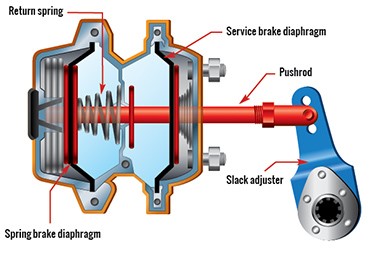
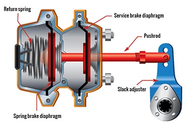
Spring brakes use a different type of brake chamber from service brakes. A brake chamber that includes both service brake and spring brake sections is called a spring brake chamber. Spring brake chambers apply the brakes by means of a large coil spring that provides enough force to hold the brakes in the applied position, instead of using air to apply the brakes.
Spring brake chambers are different in appearance from service brake chambers. To accommodate the large coil spring, a section must be added to the service brake chamber that is clearly visible and adds significantly to its size. The spring brake section is “piggy-backed” onto the service brake section and these two sections function as two separate chambers. The portion nearest the pushrod end is the service brake section and it works in the same manner as a separately mounted service brake chamber.
To release the spring brakes, normally about 414 kPa (60 psi ) of air pressure must be supplied to the spring brake chamber to compress or “cage” the spring (See Diagram 4-1). If system pressure is below 414 kPa (60 psi ), the spring brakes start applying because there is no longer enough pressure to keep them released (See Diagram 4-2).
Many vehicles can still be driven even with the spring brakes applied because they do not have the braking power of the full service brake application. Before driving the vehicle, it is important to ensure that the air brake system has enough air pressure (normally 414 kPa (60 psi )) to keep the spring brakes from applying. Due to the way most spring brake chambers are currently constructed, it is very difficult to unintentionally release the spring.
The large coil spring used in the spring brake chamber is compressed under very high tension. Tampering, damage or corrosion can cause the spring to release, resulting in sudden violent motion of parts of the air brake chamber. Since this can be hazardous, never attempt to service or repair any air brake chamber.

Diagram 4-1: Spring brake chamber - Brake not applied

Diagram 4-2: Spring brake chamber - Brake applied
Using a "caging bolt" or other mechanism, a technician can manually compress or "cage" the spring in a spring brake chamber. This may be necessary to move a vehicle in an emergency. When a spring brake chamber fails, a technician may use the manual caging method to temporarily disable it. A spring brake chamber that has been disabled by this method looks different and the parking and emergency brake will not apply. Disabled or caged spring brake chambers can be recognized by the protrusion of the caging bolt or other similar mechanism. Drivers encountering a disabled spring brake chamber should have the vehicle inspected and repaired immediately.
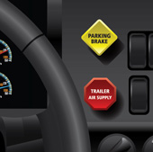
A spring brake control valve is normally a push/pull type valve fitted with a yellow, four-sided knob located near the driver (See diagram 4-3). Most spring brake control valves are pushed to supply air and release the spring brakes, then pulled to exhaust air and apply the spring brakes. Some vehicles may have this function reversed, but its functions are normally described on or near the control valve. Some vehicles use a toggle type valve for this purpose. Drivers must be familiar with the type of control valve used in their vehicle.
Some trucks and tractors may also have a separate control called a tractor parking-brake control valve to release the spring brakes on the tractor while keeping the trailer spring brakes applied. This optional control valve normally has a round blue knob.
Spring brake control valves are designed to respond to air brake system pressure dropping below a certain level (normally 414 kPa or 60 psi ) by exhausting the remaining air that is holding the spring brakes in the released position. This causes sudden automatic application of the spring brakes and an uncontrolled vehicle stop. The control valve knob will pop out when this occurs.
Important: If air brake system pressure drops below its normal operating range (normally 414 kPa or 60 psi ), the spring brakes will automatically begin to apply.
In an emergency when the service brakes fail, the spring brakes can be applied by using the spring brake control valve.
The effectiveness of a vehicle’s spring brakes depends on the condition of the brakes and proper brake adjustment. If brakes are out of adjustment, the spring brakes may not stop or hold a vehicle stationary.
Remember: Poor brake adjustment reduces the ability of service brakes to stop a vehicle and reduces the ability of spring brakes to stop or hold a vehicle.

Diagram 4-3: Spring brake control valve
Many buses and motor coaches are fitted with parking and emergency brakes that do not use a large spring in the brake chamber. This type of chamber is called a DD3 Safety Actuator. Although similar to a spring brake chamber, a DD3 brake chamber has three air line connections instead of two. Internally, these chambers have a mechanical means of locking a brake in the applied position. A control valve similar to the one used in conventional spring brake systems applies the emergency and parking brakes. Releasing the spring brakes requires operating the control valve and then pressing the brake pedal for three to five seconds.